
Part of a series of videos and blogs tracking the development of The Groundhog, which was entered into the MAAXX Europe 2017 competition earlier this year.
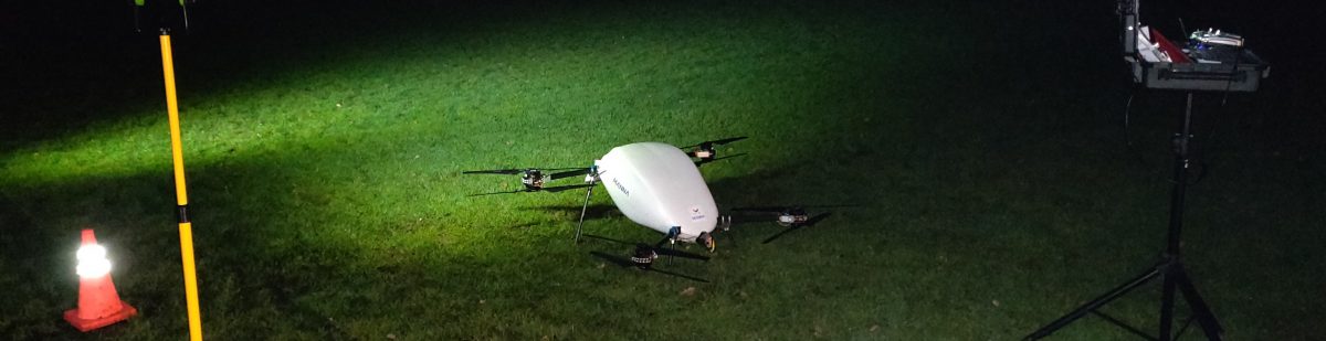
Having successfully tested the re-written code to follow straight lines using velocity vectors for control and NED space mapping for line detection, we test it around a 50m track comprising 50mm wide red webbing – and we speed it up a bit as well.