
What’s this About
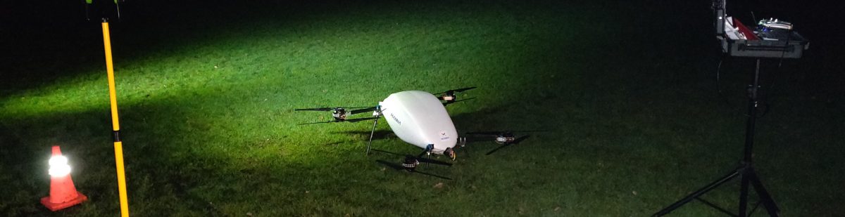
I’m rebuilding The Groundhog to a more professional level, with the level of accuracy required for the AI and computer vision work planned. It’s also getting an upgrade to the avionics to make it more resilient. This post details the rebuild and also has links to the 3D printed parts used.
Airframe and Power Train
The airframe and power train has proved capable and reliable over the last 18 months, so it is being retained. It comprises:
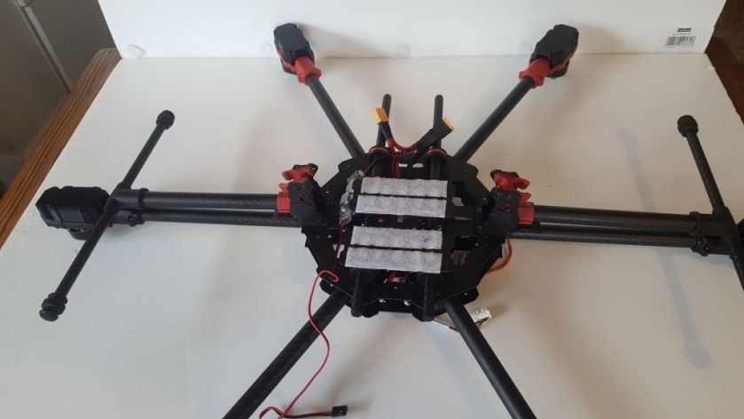
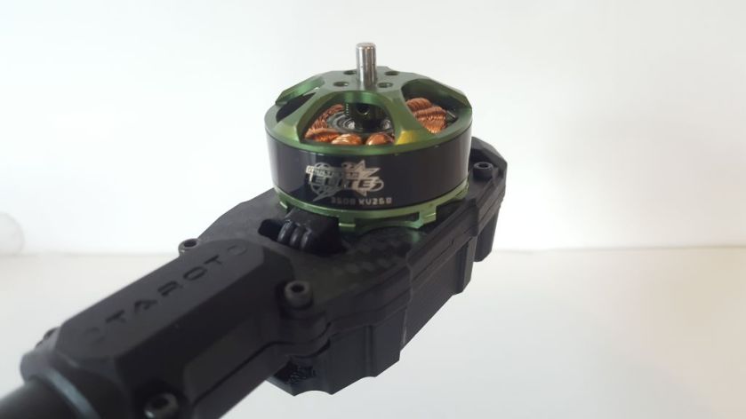
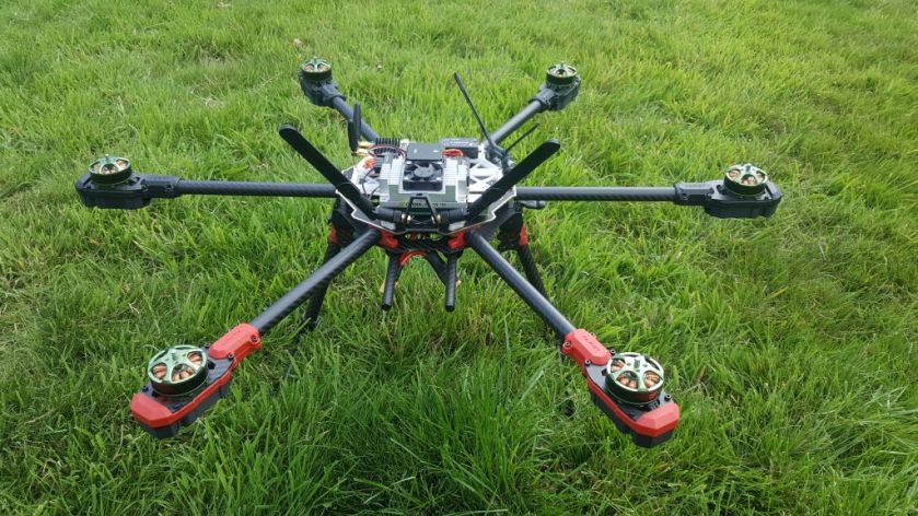
- Tarot 680 Pro Hexacopter airframe
- 2 x 4S 8000mAH Lipos (connected in series)
- 6 x Afro 20A HV Multi-rotor ESC High Voltage 3~8s
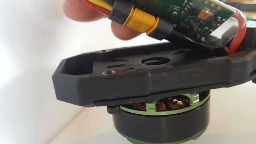
- 6 x Multistar Elite 3508-268KV High Voltage Endurance Motor
This flies smoothly, stands up to windy conditions and gives about 30 minutes flight time.
Avionics
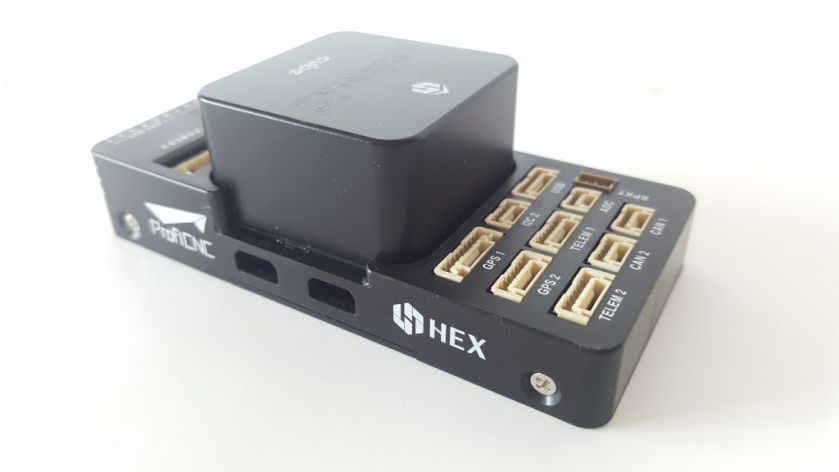
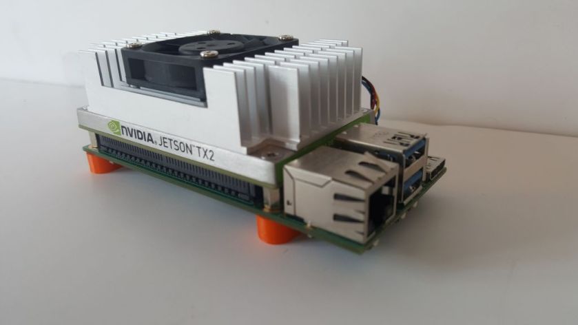
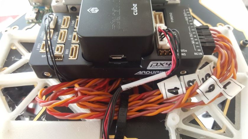
The old Pixhawk is being replaced with a Pixhawk 2 for the overall improved build quality and resilience. The Raspberry Pi companion computer is being replaced by an NVIDIA Jetson TX2. I have flown the TX2 for a previous blog, mated to an Intel D435 depth camera. But to do this, the entire TX2 development board was mounted to the hexacopter – somewhat clumsy, if effective! This time, the TX2 will be mounted on an Auvidea J120 carrier board.
Assembly
Part of the more professional build is about reducing the traditional reliance on double sided tape, Velcro/dual lock and cable ties. Let’s see how we do…
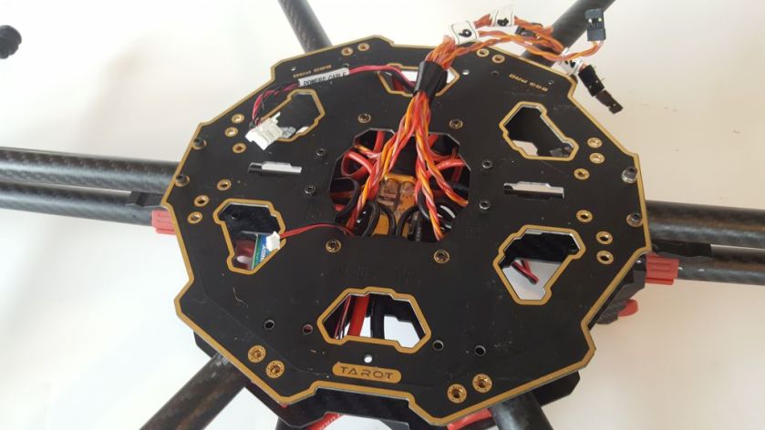
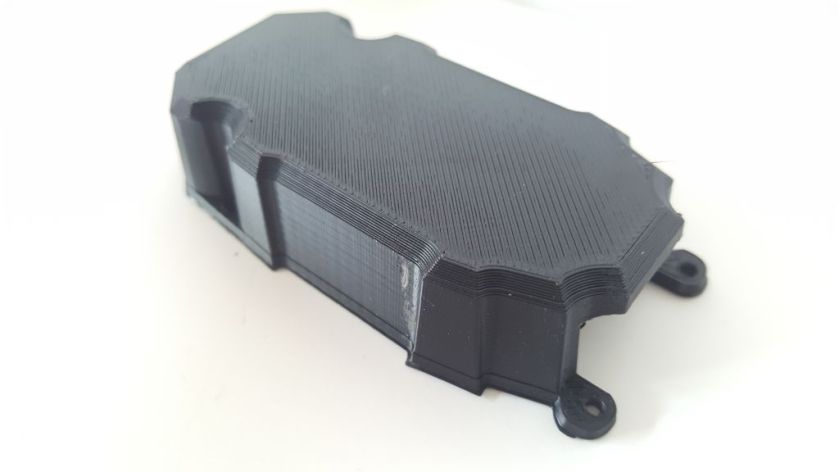
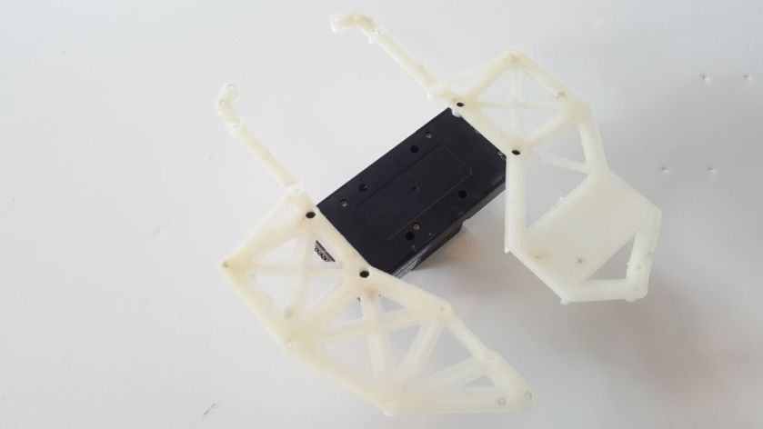
Drilling the hexacopter top plate is a non-starter as it doubles-up as the power distribution board. The solution is to mount the components on a separate frame, in this case 3D printed from a nylon based plastic, selected for it’s strength over ABS and PLA.

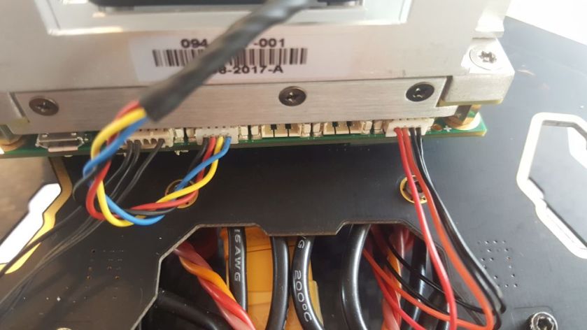
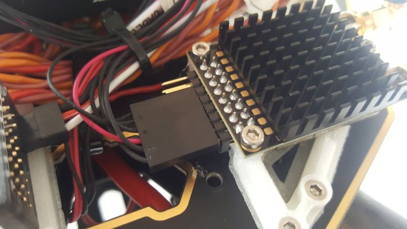
Before the TX2 can be mounted, it’s power lead and the serial lead to the Pixhawk must be connected. A small change needs to be made to the serial lead, as follows:
- Use the TELEM2 lead supplied with the Pixhawk2.
- Pixhawk side, remove the 5V, CTS and RTS wires.
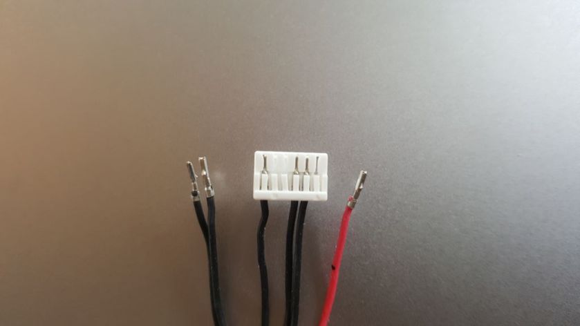
- Follow the disconnected wires through to the TX2 DF13 connector and remove them.
- The ground wire (rightmost, below) is already correctly positioned.
- Reverse the remaining TX and RX wires.
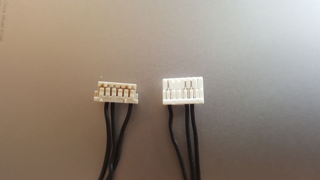
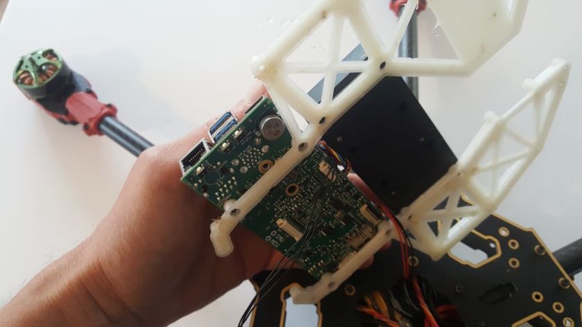
I have learned to be wary of all beige-colour DF13 connectors, as supplied in this case. I have previously found them almost impossible to push into a socket. Sure enough, this proved to be the case on attempted insertion into the J120 carrier board. The solution is to trim off the tabs on the left and right sides (image above previous to this).
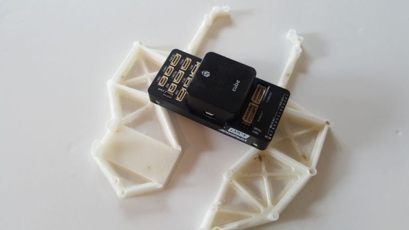
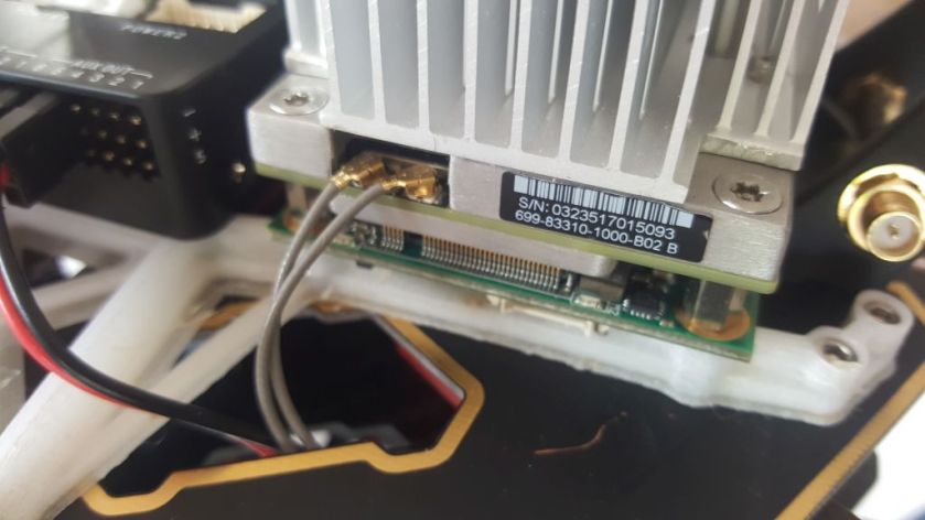
OK, so the leads are plugged into the J120 carrier board and we can bolt the TX2 down to the frame using the screws supplied with the carrier board itself. This has to be done from underneath, similar to the Pixhawk2.
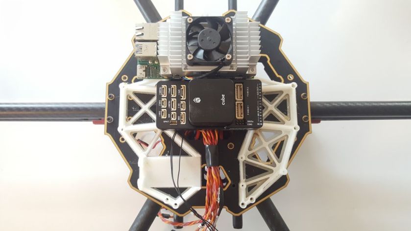
Now bolt down the frame.
Wiring and Peripherals
Consistent with the general upgrade, the following peripherals are being used:
- Here GNSS GPS
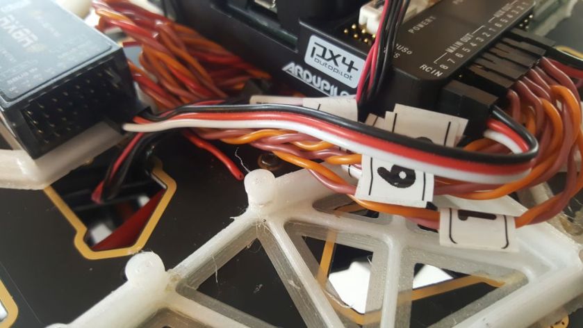
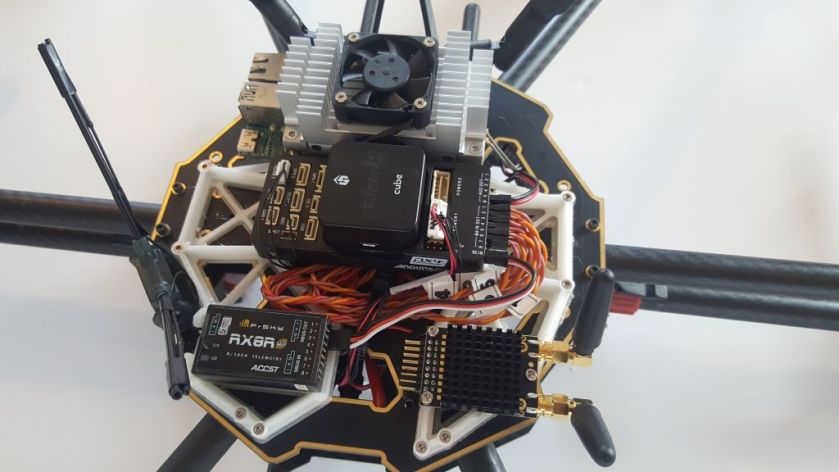
- FrSky RX8R receiver
- RFDesign RFD868x telemetry set
- Turnigy 5A (8-26v) SBEC for Lipo (6V supply to servo rail)
- Quanum 12V-5A (7.2 – 25.2V) Dual Output UBEC (12V supply to TX2)
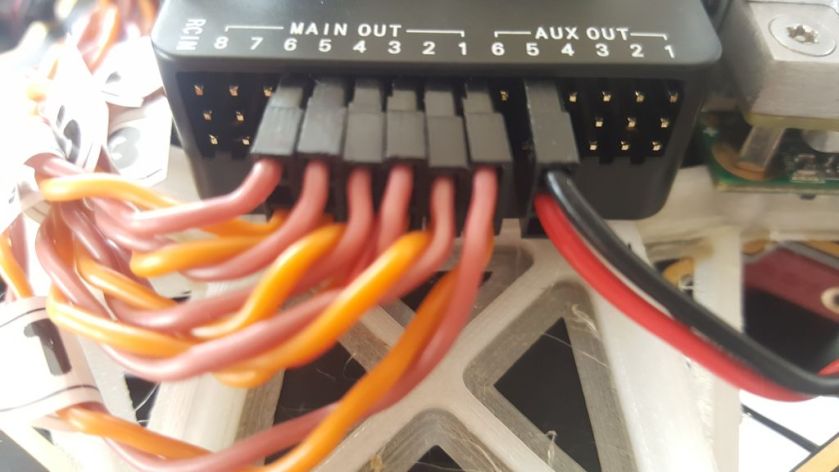
First connect the ESCs to the Pixhawk2.
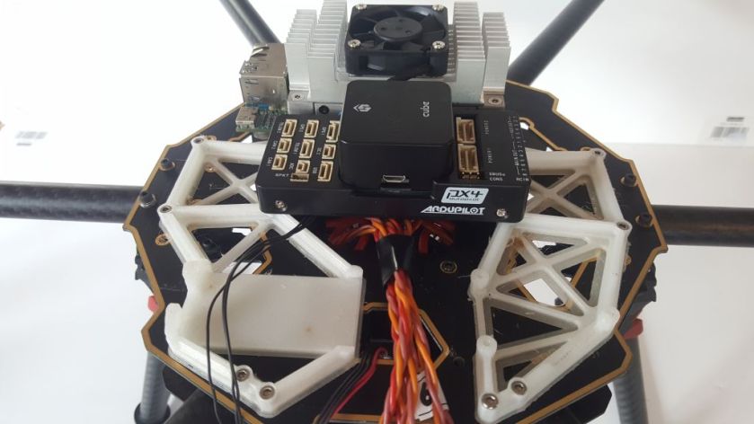
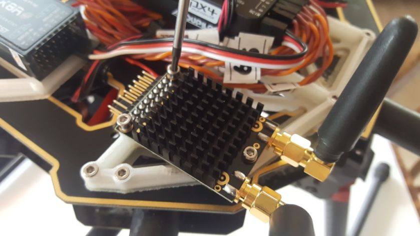
Mount the various antennae (receiver, TX2, telemetry unit).
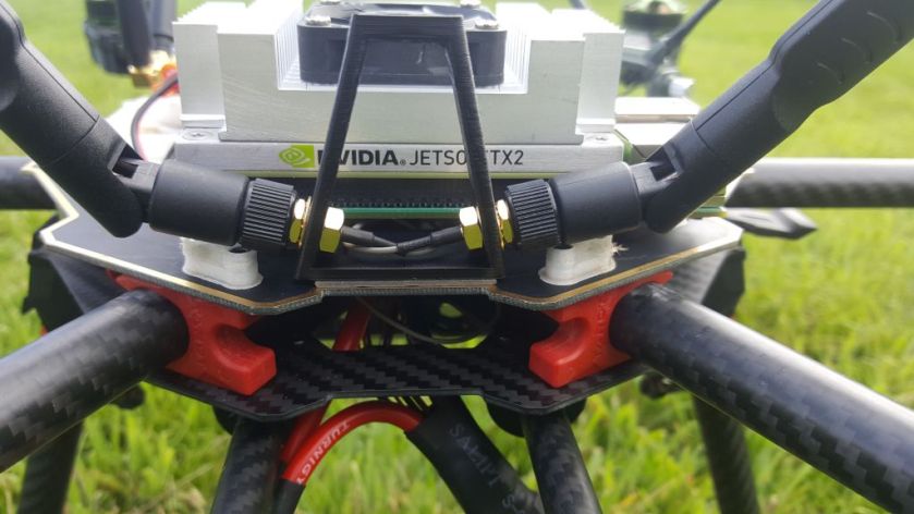
All that’s left is the GPS, which can be mounted on a standard pole. However, I am making a simple frame from nylon to do mount the Here GNSS unit which will also afford some knock-protection. It is functional, if not beautiful…
What’s Next
Obviously the system needs to be tested before it can be flown. In addition to the usual configuration settings, I am keen to check the settings on the telemetry unit to ensure the power output is legal in the UK.
Development
In the first instance, the Pixhawk2/TX2 platform will mirror the progression in my series on ROS development, which is geared at the moment to a (regular) Pixhawk/Raspberry Pi system. However, the development paths will diverge soon when we start to use the ability of this platform to utilise advanced cameras and machine learning.
